Issue:
Product Design Features
Product Line:
QO and Homeline Load Centers
Resolution:
The PK9GTA through PK27GTA(L) will install ONLY in Square D QO and Homeline convertible main, 100 - 225 A load centers.
See FA126819 for all the PK ground bar wire sizes and torque specifications.
The featured video is ONLY to supplement the INSTRUCTIONS that come with each PK ground bar kit.
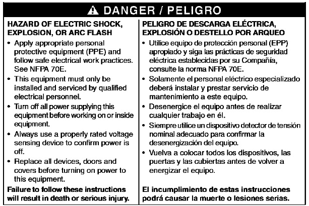
PLEASE make sure to read and follow the instructions that come with each PK ground bar kit and all the below safety information that is located in the instructions BEFORE working on any electrical equipment.
A PDF file is attached from the load center catalog section showing all the PK ground bar dimensions.

Each of the load center enclosures will have 3 separate ground bar mounting locations inside the enclosure, one location on the left side, one on the right side, and on at the bottom of the interior.
Each ground bar mounting location will be marked with a stamped ground symbol and will have 'anti-turn nubs' at that location in the enclosure and a mounting hole where the PK ground bar will be mounted.
Each of the ground bars within the range noted above will come with the appropriate mounting screws and torque label.
Make sure to turn OFF ALL power supplying the equipment and verify the power is OFF using a properly rated voltage sensing device BEFORE working on or with electrical equipment.
1) Once all Safety steps are followed, begin the kit installation by following the instructions.
2) Remove Cover from load center.
3) Mounting ground bar to back of the Enclosure (A) see Figure on top of page two of instructions.
a) If one mounting hole and two nubs are provided, mount grounding bar (B) with 2 outer mounting holes over nubs and one mounting screw (C) through center mounting hole. See Figure on page 2 of instructions.
b) If two mounting holes are provided, mount ground bar (B with two mounting screws (C) See Figure on page 2 of instructions.
NOTE: If No mounting holes are provided, use a #26 drill bit to drill two 0.147 in (3.7mm) diameter mounting holes using the grounding bar as a drilling template. DO NOT allow metal shavings to fall onto the interior components. Actually it might be a good idea that if for some reason holes need to be drilled, then remove the interior BEFORE drilling any holes. Once holes are drilled, re-install the interior.
4) Apply equipment grounding label to the enclosure beside the grounding bar.
5) Install wiring to ground bar. See equipment grounding label for binding screw torque.
Product Design Features
Product Line:
QO and Homeline Load Centers
Resolution:
The PK9GTA through PK27GTA(L) will install ONLY in Square D QO and Homeline convertible main, 100 - 225 A load centers.
See FA126819 for all the PK ground bar wire sizes and torque specifications.
The featured video is ONLY to supplement the INSTRUCTIONS that come with each PK ground bar kit.
PLEASE make sure to read and follow the instructions that come with each PK ground bar kit and all the below safety information that is located in the instructions BEFORE working on any electrical equipment.
A PDF file is attached from the load center catalog section showing all the PK ground bar dimensions.
Each of the load center enclosures will have 3 separate ground bar mounting locations inside the enclosure, one location on the left side, one on the right side, and on at the bottom of the interior.
Each ground bar mounting location will be marked with a stamped ground symbol and will have 'anti-turn nubs' at that location in the enclosure and a mounting hole where the PK ground bar will be mounted.
Each of the ground bars within the range noted above will come with the appropriate mounting screws and torque label.
Make sure to turn OFF ALL power supplying the equipment and verify the power is OFF using a properly rated voltage sensing device BEFORE working on or with electrical equipment.
1) Once all Safety steps are followed, begin the kit installation by following the instructions.
2) Remove Cover from load center.
3) Mounting ground bar to back of the Enclosure (A) see Figure on top of page two of instructions.
a) If one mounting hole and two nubs are provided, mount grounding bar (B) with 2 outer mounting holes over nubs and one mounting screw (C) through center mounting hole. See Figure on page 2 of instructions.
b) If two mounting holes are provided, mount ground bar (B with two mounting screws (C) See Figure on page 2 of instructions.
NOTE: If No mounting holes are provided, use a #26 drill bit to drill two 0.147 in (3.7mm) diameter mounting holes using the grounding bar as a drilling template. DO NOT allow metal shavings to fall onto the interior components. Actually it might be a good idea that if for some reason holes need to be drilled, then remove the interior BEFORE drilling any holes. Once holes are drilled, re-install the interior.
4) Apply equipment grounding label to the enclosure beside the grounding bar.
5) Install wiring to ground bar. See equipment grounding label for binding screw torque.
Released for:Schneider Electric USA


